
- English
- Español
- Português
- русский
- Français
- 日本語
- Deutsch
- tiếng Việt
- Italiano
- Nederlands
- ภาษาไทย
- Polski
- 한국어
- Svenska
- magyar
- Malay
- বাংলা ভাষার
- Dansk
- Suomi
- हिन्दी
- Pilipino
- Türkçe
- Gaeilge
- العربية
- Indonesia
- Norsk
- تمل
- český
- ελληνικά
- український
- Javanese
- فارسی
- தமிழ்
- తెలుగు
- नेपाली
- Burmese
- български
- ລາວ
- Latine
- Қазақша
- Euskal
- Azərbaycan
- Slovenský jazyk
- Македонски
- Lietuvos
- Eesti Keel
- Română
- Slovenski
- मराठी
- Srpski језик

How Do You Choose the Right Power Battery Charger for an Electric Vehicle?
Choosing a charging unit involves more than comparing its rated power. Battery chemistry, voltage range, charging current, vehicle architecture, cooling, environmental protection, communication, and installation conditions all affect compatibility. This guide explains how to assess these factors, distinguish on-board and off-board equipment from DC/DC conversion, and prepare a clear specification before selecting a charging solution for an electric vehicle or industrial platform.
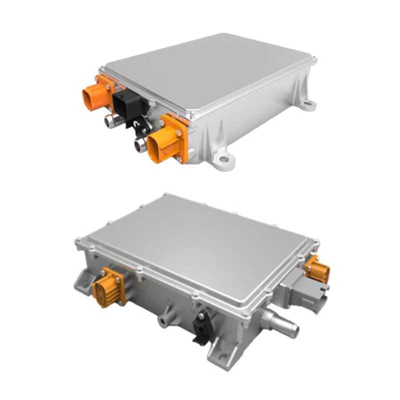
Table of Contents · Explore the guide
- What Does a Charging System Actually Do?
- Which Charging Architecture Fits the Vehicle?
- How Do You Match Ratings to the Battery?
- Which Operating Conditions Matter?
- What Should Be Checked Before Integration?
- Which Selection Mistakes Should You Avoid?
- What Should a Practical Checklist Include?
- Frequently Asked Questions
What Does a Charging System Actually Do?
A vehicle charging system transfers electrical energy from a power source into a battery under controlled conditions. Its job is not simply to deliver current. It must operate within the battery pack's permitted voltage and current limits, respond to charging requests, manage heat, and coordinate with the vehicle's electrical controls.
A correctly selected Power Battery Charger should therefore be evaluated as part of the complete electrical architecture. The battery pack, battery management system (BMS), wiring, connectors, thermal design, and control network all influence how charging works in real operating conditions.
The first step is to identify the system's purpose. A passenger electric vehicle may use an on-board unit for AC charging, while a warehouse vehicle may connect to an external charger during a scheduled charging period. Some platforms also need a DC/DC converter to provide a suitable voltage to low-voltage electrical loads.
Core principle: Rated power describes only one part of a charging system. Compatibility depends on the relationship between the battery, charger, vehicle controls, and the environment in which the equipment operates.
Which Charging Architecture Fits the Vehicle?
Charging equipment is often grouped by where energy conversion takes place and what the unit is designed to supply. Clarifying these functions prevents a common selection error: comparing products that perform different jobs as though they were interchangeable.
On-board charger (OBC)
An OBC is installed in the vehicle. It converts incoming AC power into DC power that the battery can accept, subject to the limits defined by the battery and its control system. Packaging, mounting, vibration, cooling, connector placement, and the vehicle's available AC input all matter when evaluating an on-board design.
OBC selection should start with the vehicle's supported charging interface and battery voltage window. The physical envelope and thermal path should then be checked against the installation space. An OBC with suitable output ratings may still be unsuitable if its connector arrangement, cooling requirements, or communication interface does not match the vehicle.
Off-board charger
An off-board unit is installed outside the vehicle and supplies controlled DC power through a charging connection. This architecture can suit equipment that returns to a charging bay or uses a dedicated external charging station. The system specification should define the DC output range, current limits, connector, charging protocol, and how the unit receives permission to charge.
For industrial vehicles, the charging location is part of the design. Consider the available electrical supply, cable routing, operator access, ventilation, exposure to dust or moisture, and whether the charger will remain in one place or be moved between work areas.
DC/DC converter
A DC/DC converter changes one DC voltage level to another. In an electric vehicle, it may supply a low-voltage network from a higher-voltage battery. It is not automatically a substitute for an OBC or an external battery charger, because its intended input, output, controls, and charging function may be different.
Bidirectional converters add another layer of system requirements. The specification must state the permitted power-flow directions, voltage windows, control logic, and protective behavior in each operating mode. Do not assume bidirectional operation from a product name alone.
| Equipment Type | Primary Function | Key Selection Questions |
|---|---|---|
| On-board charger | Converts vehicle AC input to battery-compatible DC power. | Does the AC input, DC output range, mounting envelope, cooling method, and communication interface match the vehicle? |
| Off-board charger | Provides controlled DC charging from equipment outside the vehicle. | Are the output voltage, current, connector, charging protocol, and site conditions compatible? |
| DC/DC converter | Converts DC power between voltage levels for vehicle electrical systems. | Are input and output ranges, continuous load, direction of power flow, and control requirements correct? |
How Do You Match Ratings to the Battery?
Electrical ratings should be checked against the battery manufacturer's limits and the vehicle's operating profile. A label showing a nominal voltage or rated power does not describe every condition under which a charger can operate.
When reviewing a Power Battery Charger, request the complete input and output ranges rather than relying on a single headline value. Check whether the published values refer to continuous operation, a specific cooling condition, or a defined operating point.
Battery chemistry and charging profile
Battery chemistries can have different charging limits, temperature restrictions, and control requirements. Even batteries described by the same nominal voltage may require different charging profiles. Confirm the exact battery chemistry, pack configuration, permitted voltage range, maximum charging current, and any temperature-dependent limits before choosing equipment.
The BMS may communicate charging limits dynamically. The charger and vehicle controls must interpret these requests correctly and enter a safe state when the battery signals a fault or when communication is lost. A charging profile should never be selected solely from the battery's nominal voltage.
Voltage, current, and power
Output voltage must cover the battery's required operating range. Output current determines how much charging current can be delivered within that range, while rated power describes the maximum electrical output under the stated conditions. These figures are related, but they are not interchangeable.
Check the minimum and maximum output voltage, continuous current, peak or temporary limits if applicable, and derating behavior. A unit may not maintain its highest output power across the entire voltage range or at every ambient temperature. Ask for a rating curve or operating envelope if the vehicle must work near the limits.
Input supply and installation constraints
Record the available AC or DC input, phase configuration where relevant, frequency range, connector type, grounding arrangement, and upstream protection. The input source must be compatible with the charger's specified operating range. For a mobile or off-board unit, also consider whether the power supply changes between sites.
| Parameter | Information to Confirm | Why It Matters |
|---|---|---|
| Battery chemistry | Battery type and approved charging profile. | Helps ensure that the charging method matches the battery's operating limits. |
| Nominal and working voltage | Nominal voltage plus minimum and maximum pack voltage. | Confirms that the charger can operate across the required range. |
| Charging current | Maximum continuous current and any current limits communicated by the BMS. | Helps prevent mismatches between charger output and battery requirements. |
| Rated output power | Continuous output rating, operating conditions, and derating curve. | Clarifies expected performance under actual voltage and temperature conditions. |
| Input supply | AC/DC type, voltage range, phase, frequency, and connection details. | Checks whether the charging equipment can be connected to the available supply. |
| Communication | Protocol, message definitions, control signals, and fault response. | Supports coordination between the charger, BMS, and vehicle controller. |
Which Operating Conditions Matter?
A charger operates within a physical environment, not just an electrical diagram. Ambient temperature, cooling airflow, water exposure, dust, vibration, installation orientation, and available space can influence reliability and output capability. A Power Battery Charger should be assessed against the conditions of its actual installation, not only its nominal electrical ratings.
Cooling and thermal derating
Air cooling and liquid cooling solve thermal-management needs in different ways. Air-cooled designs depend on the movement of air and the ability to release heat through the specified path. Liquid-cooled designs require compatible coolant connections, a suitable circulation arrangement, and attention to service access and leak management.
Choose the cooling method from the unit's technical requirements and the vehicle's available resources. Confirm whether airflow must remain unobstructed, whether a pump or external cooling circuit is needed, and how output changes as temperature rises. A high rated output is useful only when the complete installation can sustain it.
Ingress protection and temperature range
An IP rating describes protection against defined ingress conditions. It should be checked for the exact model and installation configuration rather than assumed across an entire product family. The rating alone does not mean equipment can tolerate every outdoor condition, chemical exposure, pressure wash, or installation method.
Compare the stated operating temperature range with the actual site conditions, including heat inside a closed enclosure and cold starts after the vehicle has been parked. If a unit is expected to operate in rain, wash-down areas, dusty warehouses, or outdoor yards, confirm the applicable protection level and installation restrictions.
Mechanical fit and service access
Review the dimensions, mounting points, cable bend radius, connector clearance, weight, and access required for inspection or replacement. A physically compact charger can still create a difficult installation if a cable cannot be routed safely or if cooling surfaces are blocked by adjacent components.
For fleet and industrial applications, document where the charger will be located during use and where routine inspection will take place. The design should allow the specified connectors, protective devices, and cooling components to be checked without creating unnecessary interference with nearby equipment.
What Should Be Checked Before Integration?
Electrical compatibility is only one part of a complete installation. The charging unit must also exchange the right information with the battery and vehicle, respond predictably to faults, and meet the applicable requirements for the final product and its intended market.
- Communication: Confirm whether CAN or another interface is required, which messages are exchanged, and how timeouts or invalid data are handled.
- Protective functions: Clarify overvoltage, overcurrent, overtemperature, short-circuit, insulation, and other protections that apply to the specific system.
- Control sequence: Define startup, charging permission, current adjustment, normal shutdown, emergency interruption, and restart behavior.
- Connectors and cabling: Confirm pin assignments, cable ratings, polarity, grounding, strain relief, and mating connector compatibility.
- Mechanical and thermal interface: Review mounting, enclosure conditions, cooling connections, airflow, and maintenance clearance.
- Compliance documents: Identify the standards, certification marks, test records, and documentation required for the finished vehicle or equipment.
- Technical support: Agree on the information needed to diagnose a fault, including status codes, event logs, and operating conditions.
Documentation should be model-specific. Ask for the current datasheet, dimensional drawing, connection definition, communication specification, installation instructions, and available test or compliance documents that apply to the exact configuration under consideration.
When reviewing a Power Battery Charger for a new vehicle or a replacement project, share the system requirements before finalizing the model. This makes it easier to identify interface differences early, rather than discovering them after mechanical parts, harnesses, or control software have been prepared.
Which Selection Mistakes Should You Avoid?
Several recurring mistakes can lead to an unsuitable charging unit even when its headline rating appears correct.
- Choosing by nominal voltage alone: A matching nominal value does not prove that the full battery voltage window and charging profile are supported.
- Confusing equipment functions: An OBC, off-board charger, and DC/DC converter perform different roles. Confirm the required energy-conversion path before comparing models.
- Ignoring derating: Maximum output may depend on input voltage, ambient temperature, cooling conditions, or the current operating point.
- Assuming all protection ratings are the same: Environmental ratings can differ among models and configurations. Verify the selected unit's actual specification.
- Leaving communication until late in development: Electrical ratings cannot compensate for incompatible messages, connector pinouts, or control sequences.
- Overlooking the real duty cycle: Repeated charging, extended operation, idle periods, and varying site conditions may produce different thermal demands.
- Relying on incomplete documents: A short catalogue description is not a substitute for the datasheet, wiring details, interface requirements, and installation limits.
The best way to reduce these risks is to convert the vehicle's requirements into a written specification. Each requirement should be marked as confirmed, unresolved, or not applicable, with a corresponding document or engineering decision where needed.
What Should a Practical Checklist Include?
Before requesting a model recommendation, prepare a compact specification that covers the battery, vehicle, power source, operating environment, and control interfaces. The following sequence can help a project team organize the information.
- Define the application: Record the vehicle or equipment type, charging location, duty cycle, and whether the charger is installed onboard or externally.
- Document battery limits: Specify chemistry, nominal voltage, operating voltage range, maximum permitted current, and BMS charging requirements.
- Set the input and output envelope: List available supply conditions and required charging output, including continuous ratings and any relevant derating conditions.
- Confirm interfaces: Identify connectors, pin assignments, communication protocols, control signals, and expected responses to faults or communication loss.
- Describe the environment: Provide ambient temperature, exposure to moisture and dust, vibration, enclosure conditions, cooling resources, and available mounting space.
- List compliance needs: Specify relevant market requirements, vehicle-level standards, required documentation, and any customer-defined validation tests.
- Review the exact configuration: Check the model number, datasheet revision, wiring details, mounting drawing, cooling method, and protection rating before approving integration.
This checklist helps engineering and procurement teams discuss the same requirements. It also creates a clear record of which parameters have been agreed and which still need technical evaluation.
For different vehicle platforms, keep a separate specification for each battery and operating environment. Similar-looking vehicles may use different battery packs, communication protocols, charging connectors, or thermal arrangements, so assumptions should not be carried from one project to another without verification.
Frequently Asked Questions
Is an on-board charger the same as an off-board charger?
No. An on-board charger is installed in the vehicle and commonly converts incoming AC power into DC power for the battery. An off-board charger is located outside the vehicle and supplies controlled charging power through an external connection. The correct architecture depends on the vehicle design, charging interface, installation requirements, and intended operating pattern.
Can a DC/DC converter replace a battery charger?
Not by default. A DC/DC converter changes one DC voltage level to another, often to supply a vehicle's low-voltage network. A battery charger must provide the charging behavior required by the battery and coordinate with the relevant control system. Confirm the intended function, operating limits, and control interfaces before treating one device as a substitute for another.
Which battery information is needed before selecting a charger?
At minimum, identify the battery chemistry, nominal and working voltage range, maximum charging current, charging profile, temperature limits, and BMS interface. Also provide relevant pack-level restrictions and connector details. These parameters allow the charger output and control functions to be assessed against the battery's approved operating limits.
Does a higher rated power always mean faster charging?
No. Actual charging power is constrained by the battery's permitted current and voltage, BMS requests, charger operating limits, input supply, thermal conditions, and other system restrictions. A higher nameplate rating does not guarantee that the battery can accept that level of power throughout the charging process.
How should environmental protection be verified?
Check the exact model's IP rating, specified operating temperature range, cooling requirements, mounting orientation, and any limits on exposure to water, dust, vibration, or other site conditions. Confirm whether the rating applies to the installed configuration and whether additional enclosure or installation measures are required.
What should be included in a request for technical selection?
Include the application, battery specifications, input supply, required output range, charging current, mounting constraints, ambient conditions, cooling method, connectors, communication protocol, and applicable compliance requirements. Drawings and interface documents help clarify details that cannot be established from a short product description.
Discuss Your Charging Requirements
Share the battery specifications, input and output requirements, vehicle layout, communication interface, and operating environment for a focused technical discussion. The product team can then review the application details and help identify which configuration should be evaluated further.
Learn more about Zhaofeng and its charging equipment range, or send the project requirements directly to the team.
Contact us